Examine the Possibility of Increasing the Size of Openings According to Seismic Behavior of Masonry Structures Isolated with Sliding Layer Compared with the Fixed Structures Under Naqan Earthquake
Mohammad Javad Ebrahimi1 * and Sayed Ali Reza Mozaheb1
http://dx.doi.org/10.12944/CWE.10.Special-Issue1.01
Masonry buildings have a large share in the context of large and small towns, For example, in the city of Bam more than 90 percent of the buildings with brick and masonry structures, which are about 40% of the amount of masonry structures. According to reports, all masonry buildings are damaged in the earthquake of 20 to 100 percent. Research shows that the bulk of the damage to buildings caused by non-compliance with the provisions of the Building Regulations 2800, including the opening of the wall, the opening in the wall, resulting space restrictions, the wall of the building and etc. In this paper, a masonry structures under earthquake made great naqan modeling the structures in abaqus software in the form of macro, and the first to be connected and then a layer of sand sliding sought to separate the topside of the use and analyzed them. After this, the effect on the seismic behavior of the proposed system and create havoc in the corners of the openings are possible. Find answers to the two-state system; it is found that the proposed isolation system, while considerably reducing damage, the size of the openings can be considered more of a standard.
Copy the following to cite this article:
Ebrahimi M. J, Mozaheb S. A. R. Examine the Possibility of Increasing the Size of Openings According to Seismic Behavior of Masonry Structures Isolated with Sliding Layer Compared with the Fixed Structures Under Naqan Earthquake. Special Issue of Curr World Environ 2015;10(Special Issue May 2015). DOI:http://dx.doi.org/10.12944/CWE.10.Special-Issue1.01
Copy the following to cite this URL:
Ebrahimi M. J, Mozaheb S. A. R. Examine the Possibility of Increasing the Size of Openings According to Seismic Behavior of Masonry Structures Isolated with Sliding Layer Compared with the Fixed Structures Under Naqan Earthquake. Special Issue of Curr World Environ 2015;10(Special Issue May 2015). Available from: http://www.cwejournal.org?p=737/
Download article (pdf)
Citation Manager
Publish History
Introduction
Most cities in the world with natural disasters such as earthquakes are facing. It is usually by making in the privacy of the fault and negligence of criteria and standards for the construction, be intensified. Being Iran in the Alps and Himalaya organic belt, which is one of the world's youngest organic zones, make, Iranian plateau in terms of seismicity be very active [Yazdanbakhsh, 2004]. According to the data available , in every 10 years in Iran between 2 to 3 earthquake greater than seven, 12 and 25 earthquakes between six and seven, 160 to 200 earthquakes between five and six, and 1,200 to 1,500 earthquakes between four and five on the Richter scale occurs [Mahdavifar et al., 2010].
About 70 percent of the buildings in large cities and in small towns about 90 percent of the buildings are of masonry structures [Eshghi et al., 2003]. For example, in the city of Bam more than 90 percent of the buildings have brick and masonry structures, which are about 40% of the amount with masonry structures [Eshghi et al., 2003]. According to reports, all masonry buildings are damaged in the Bam earthquake of 20 to 100% [Eshghi et al., 2003]. Research shows that the bulk of damage incur to masonry structures caused by non-compliance with the provisions of the bylaws 2800, such as the area than the area of the wall, the length of opening ratio of the length of the wall, resulting space restrictions, length of the wall than area of the building, and so on [Yazdanbakhsh, 2004 and Eshghi et al., 2003]. Design methods and technologies in the implementation of earthquake resistant buildings, has made significant progress in the recent years. One of these methods is the isolation structures, considering the age and experience of the world in many cases a good performance against the risks of seismic has shown, And therefore, case interest of engineers and builders are located. In our country considering to the increasing development and the growing trend of construction on the one hand, And high seismicity and considerable damage which is the other side of this issue relate to the application of this technology is considered [Publication No.523]. In general, seismic isolators can be of two types of rubber isolators and friction isolators divided. Of the isolated compound can also be used [Publication No.523 and 524].
In the friction isolator that is used in this study allows the topside to at the time relatively large earthquake on the isolator tumbles. As soon exceed the shear strength of the floor isolated from of frictional force is intended to isolators the structure will begin to slip, And thus from sending large seismic forces to structures is prevented. In this time, the frictional force resulting of isolators acts against the driving force of the earthquake and the kinetic energy is amortized.
In dry sliding friction if object with mass M and with initial velocity V0 drop on a horizontal table will eventually stop. This means that the object during its movement has a average acceleration, which is in the opposite direction. Generally mean of friction is a contact interaction between solids [Halliday et al., 2004]. Coefficient of friction to many variables, including: materials, pay levels, surface, temperature and impurity depend [Halliday et al., 2004].
Modeling of Homogenous Masonry wall
As we know, most of the analysis of masonry buildings is based on the finite element methods despite having sufficient accuracy and acceptable, due to time consuming and requires a lot of memory space for the existing actual structure is almost impossible. That's why in the past two decades, great efforts to overcome this problem, in the analysis of these buildings have been performed [Shayanfar et al., 2010]. And at least four approaches are raised. In the first approach not be made any structural model similar to that of the third quarter of the 2800 code. In the second approach is merely a dead load of member’s structure such as: wall and ceiling used in the modeling. In the third approach, masonry components with homogenous and isotropic elements are ideally. In the masonry regulations also accordance with the idea only one modulus of elasticity is introduced, which is achieved by vertical compressive strength of masonry units. It is shown that, if the modulus of elasticity of cement into blocks is less and the difference of ratio the block size into the thickness of the mortar is greater than, assuming isotropic behavior for homogenous element assumed to be less accurate. To fix the problem in the fourth approach, orthotropic and homogeneous elements offered [Salehi et al., 2011].
![Figure 1- Masonry unit homogeneous model [Salehi et al., 2011]](http://www.cwejournal.org/wp-content/uploads/2015/05/Vol10_Spe_Exam_MOHA_Fig1-150x150.jpg) |
Fig. 1: Masonry unit homogeneous model [Salehi et al., 2011] Click here to View figure |
In the figure above 2a and 2b, respectively, the horizontal and vertical dimension of masonry Blocks, and 2tv mortar thickness horizontal and vertical mortar thickness is 2tf.
Description of the Modeling in Software Abaqus
Modeling of masonry walls in numerical software is a certain complexity. Masonry wall is composed of two materials mortar and brick, which according to the nonlinear behavior of mortar and brick is very difficult to predict members heterogeneous [Mousavi et al., 2012]. Building materials behavior in two modes tension and compression of an axis is specified in the following form [Lourenco 1996].
![Figure 2 (a)- an axial tensile behavior of Masonry materials [Lourenco 1996]](http://www.cwejournal.org/wp-content/uploads/2015/05/Vol10_Spe_Exam_MOHA_Fig2-150x150.jpg) |
|
![Figure 2 (b)- an axial pressure behavior of Masonry materials [Lourenco 1996]](http://www.cwejournal.org/wp-content/uploads/2015/05/Vol10_Spe_Exam_MOHA_Fig2B-150x150.jpg) |
|
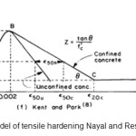
Unfortunately, the software does not have the option to define masonry materials, but there is an option to define the properties of concrete, which is capable of modeling of masonry structures. To define the wall materials used the concrete damaged plastic options. This way, is a continuous damage model which is applicable for the concrete and other brittle materials under impact uniform and went back loading, which according to the type of wall and loading conditions in this study is a good choice [Abaqus Analysis]. For the introduction of stress and strain in the software, you can use the models that are capable of modeling in abaqus software and achieve to acceptable results. In this study, for the behavior of the masonry wall pressure (Kent and Park) is used [Kent et al., 1971].
![Figure 3- Curve Kent and Park, for confined and non-confined concrete [Kent et al., 1971]](http://www.cwejournal.org/wp-content/uploads/2015/05/Vol10_Spe_Exam_MOHA_Fig3-150x150.jpg) |
|
 |
|
For the, tensile behavior of masonry materials and concrete the model of (Rasheed and Nayal) is used. This behavior defined in Figure 4.
Verification for the Modeling of the Macro Masonry Wall
For Verification and modeling of masonry walls of the lab's research Mr. Pablo et al (2008) have been used [Santa Mari et al., 2008].
In this study, six masonry wall consisting of two concrete beam above with dimensions (330 x 400 mm and 150 x 200 mm), and in bottom with dimensions (300 x 400 mm and 150 x 200 mm) that in order to transmission of load to foundation is made in accordance with figure. Horizontal loading consists of two cycles per displacement, and from 0.2 mm to 24 mm continues. The amount of displacement on condition has been that failure in sample prior, 24 mm does not appear. The value of the normal force is 98 KN. The walls in floors are connected and on the top spot with rotational freedom [Santa Mari et al., 2008].
Table1: Material properties for homogeneous wall [Santa Mari et al., 2008]
|
Em |
f’m |
Ô |
ft |
Ô |
|
6.618GP |
11.3 MP |
0.003 |
0.678 MPa |
0.0013 |
 |
|
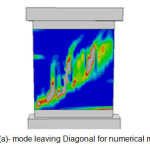
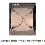 |
Fig. 5(b): mode leaving diagonal for wall experimental [Santa Mari et al., 2008 Click here to View figure |
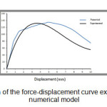
After completing the wall analysis by software, force-displacement curves of both experimental and numerical models to compare. The following figure illustrates that the behavior of the two experimental and numerical walls have acceptable consistent.
 |
|
The main Structural Modeling
In this section, we modeled several one-story structures with dimensions of 340 * 340 * 260 cm with footing beams horizontal and vertical with dimensions of 20 x 20 cm and longitudinal and transverse bars of 10 mm diameter and 6 mm and opening with the maximum dimensions and horseshoe port of concrete in accordance with Regulations 2800 [2800 Standard, 2005]. Also, a 20 cm thick concrete roof considered for the structures and put it on the horizontal footing beams of wall. These structures modeling by applying variables such as: fixed base, isolated, dimensions of opening and records of earthquake. Analysis method of the survey was to be dynamic nonlinear time history that, by applying NAQAN earthquake record in both the horizontal direction is remarkable.
In order to isolate the base of the structure, use of one another base under the main base and the coefficient of friction (friction-pure) between the foundations based on approximate and empirical values coefficients of friction between the concrete and the concrete is considered to amount to 0.2. We this coefficient in the form Contact of type Surface to Surface modeling in software.
The dead and live load according to the magazine 360 is equal to and . And according to the level of tonnage ceiling, obtain the existing overhead and on the properties of concrete roof was applied [Publication No.360].
Select and apply the properties of materials based on the table below is taken from Mr. Tasnimi reports [Tasnimi, 2004].
Table2: Properties of Materials
|
Unit masonry materials |
|
Concrete |
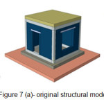 |
Fig. 7(a): original structural model Click here to View figure |
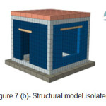 |
Fig. 7(b): Structural model isolated Click here to View figure |
As in Figure 7 (b) is remarkable, due to the separation structures of the foundation and lateral movement of the structure with imposed the earthquake record, we increasing dimensions of underlying foundation to avoid falling structure of over underlying foundation. It is noteworthy that using ideas such as the use of composite isolation system or placement of a device with restoring force can be justifiable to overcome the disadvantage of this type of system.
Comparison of Isolated Structures and Structures with Fixed Base
 |
|
 |
|
 |
|
 |
|
 |
|
 |
|
 |
|
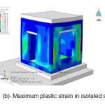 |
Fig. 11(b): Maximum plastic strain in isolated structures Click here to View figure |
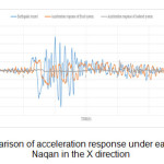
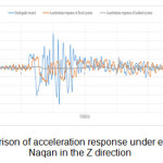
With reference to the diagrams in Figures 8, at this point we realized that after separating the structure of foundation by the sliding layer significant reduction occurred in the acceleration response of fixed system and this reduction can be an acceptable impact on the structural and non-structural damage.
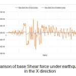
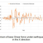
Figure 9 shows change descending (about 85%) of the maximum base shear of isolated system compared to system with fixed base, this increases the period of the isolated structure to the fixed structure and this is also an important factor in the design of masonry structures.
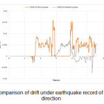
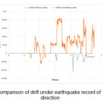
In the graphs in figure 10 paying to compares of the relative displacement between the top and bottom of the structure. It can be seen that the proposed system, the relative displacement of the structure has reduced to a value of 50% So that existing masonry structures shift has with lowest relative displacement due to earthquake. The reduction in the structural drift can be very significant impact in the creation of structural and non-structural slight damage.
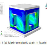
Figure 11 shows the maximum plastic strain (damage) in the both fixed and isolated structures is. Referring to Figure 11 (a) informed of how damage of structural in naqan earthquake that this failure in the isolated structures significantly reduced.
Examine the Possibility of Increasing The Level of Opening
Then to respond to the question that may be able to increase the dimensions of opening of isolated structures with sliding layer to the criteria provided in the code of 2800, isolated structures with change the opening (window) _ increased approximately 35 percent_ were re-modeling and has analyzed. The following figure indicates the maximum plastic strain in the isolated structure with the sliding layer and larger window than the standard mode.
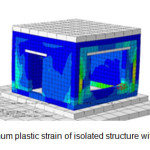 |
Fig. 12: maximum plastic strain of isolated structure with larger window Click here to View figure |
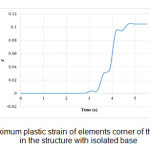
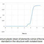
In order to assess the damage in the corner of opening a constant element (shown in Figure 12) In the each of the three models (Structure with fixed base, structure with isolated base and standard window and structure with base isolated and larger windows than the standard mode) intended and to compare the maximum plastic strain in the each of the three elements paid according to the diagrams below.
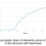 |
Fig. 13(a): maximum plastic strain of elements corner of the standard window in the structure with fixed base Click here to View figure |
 |
|
 |
|
As can be seen in figures 13, maximum plastic strain of corner elements of the window is reduced considerably by separation the structural of foundation by sliding layer. And In the case that window is larger than the standard size this amount is approximately 2 times higher than in the standard mode. But still, there is many distance with the amount of its corresponding in the fixed system. According to results to this point we realized that using the proposed separation system can be opening size increased in significant quantities without significant changes in structural damage.
Conclusions
Use the isolator layer sliding in the level of foundation has considerable influence on the structural dynamic capacity so that an isolated structure with sliding layer to a structure with similar specifications and materials and fixed base can withstand strong earthquakes. Also reduces the damage to the structure.
Use the isolator layer sliding 85 percent reduction in the amount of the maximum base shear of masonry Structures.
Using the proposed system, we can reduce the acceleration response of structures to earthquake.
The isolator layer sliding effect will be significantly in reduction of relative displacement.
The isolator layer sliding considerably reduces the damage in the opening corner.
With 30% increase in dimensions of opening, the plastic strain in the element of opening corner has increased 8%. So we can, the size of the openings in the masonry structures separated by sliding layer considered less restrictive compared to the fixed structures.
References
- Abaqus Analysis User's Manual Ver 6.13
- Eshghi, S; Zare, M. preliminary report of Bam earthquake. International Institute of Seismology and Earthquake Engineering. The fourth season. Tehran (2005)
- Halliday, D; Resnick, R; Walker, J. Fundamentals of Physics (Fourth Edition). Volume One. (2004)
- Kent, D.C; park, R. flexural Members with confined concrete, journal of structural Division, proceedings of the A1me1rican Society of civil Engineers, 97, 1969-1990(1971)
- Lourenco, P.B. Computational Strategies for Masonry Structures, Delft University Press, Portugal (1996)
- Mahdavifar, M; Izadkhah, Y.O; Heshmati, V. Appropriate and Correct Reactions during Earthquakes: “Drop, Cover and Hold on” or “Triangle of Life”; Journal of Seismology and Earthquake Engineering, 11, (2010)
- Mousavi et al. Numerical modeling of reinforced concrete frame filled with Building materials in Abaqus software, the first conference retrofitting and upgrading of urban tissue in the vicinity of active faults, Tehran (2012)
- Publication No.360. Deputy of president of strategic planning and monitoring, Instructions Improvement of existing buildings, (office administration, 2007)
- Publication No.523. Deputy of president of strategic planning and monitoring, Guide the design and implementation of isolation systems in buildings, (office administration, 2010)
- Publication No.524. Deputy of president of strategic planning and monitoring, Guide to methods and practices seismic rehabilitation of existing buildings and administrative details, (office administration, 2010)
- Regulation for designing structures against Earthquake (2800 standard), Ministry of Housing and Urban Development, Third Edition, (Housing and Building Research Institute, 2005)
- Salehi, A; Soltani, M. Homogeneous linear methods in masonry structures, International Conference on Civil Engineering, Tehran (2011)
- Santa Mari, H; Alcaino, P; Luders, C. Experimental Response of Masonry Walls Externally Reinforced With Carbon Fiber Fabrics, 8th U.S. National Conference on Earthquuake Engineering, United State (2008)
- Shayanfar, M; Tarvirdi, M. Homogenization theory for modeling the brick walls. Third National Conference on retrofitting and urban management. Tehran (2010)
- Tasnimi, A. behavior of Brick walls set forth in the 2800 standard, (Housing Research Center 2004)
- Yazdanbakhsh, M. Lessons from the Bam earthquake, (International Institute of Seismology and Earthquake Engineering 2004)